Of Airflow, Balancing, and Engineering Progress, or, What’s Inertia
Got to Do With It?
I
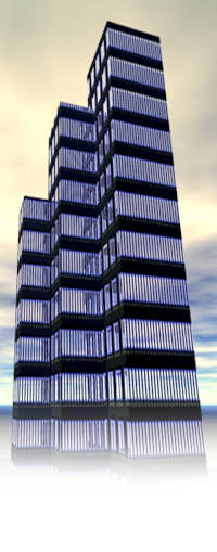
got so excited at the end of the last issue, I just couldn’t wait to show you the picture I promised (see Figure 1). While I grant you only an engineer could get excited about the kind of stuff I talk about when I get technical, it’s
my hope that the lay public in my audience finds the technical stuff at least interesting enough to avoid exclaiming, as my
fiancée has on occasion been known to, “snore.”
Anyway,
the illustration represents the latest iteration of the “Eureka” moment I spoke of in the last issue.
Way
back when, I was designing the central A/C system for Mary Tyler Moore’s 5th
Avenue co-op, and I ran across an issue where the space available to supply cooling to a corridor/art
gallery existed only above a doorway which entered the corridor near the center of one of its long walls. I designed
the branch duct feeding the outlet to keep the velocity down low enough to preclude rumble in the duct, and when I looked
for a grille in which to terminate the duct, I ended up with a grille about twice as wide as the supply duct. That’s
because grilles always have to be larger than their supply ducts in order to keep noise within limits since all the bars/louvers
in the core of a grille subtract from the free area available for discharge airflow.
So,
some distance upstream of the outlet, I designed a duct transition to gradually expand from the width of the duct to the width
of the outlet, figuring I was home free. Piece of cake, right?
Well-l-l,
not exactly. I’ll get back to this a little later.
At
about the same point in my career, I started to think there had to be a better way to feed linear diffusers than multiple
branch ducts feeding “pancake” plenums from a trunk duct stepping down in area after each branch duct. My
first whack at it was a tapered plenum like the one shown in the drawing, but with no dividers within. I’d figured
that as air exited the diffuser at its upstream end, the continuous taper would keep the pressure in the plenum high enough
to have the diffuser deliver air for its entire length. It didn’t quite work out as I’d expected.
At
first it worked well enough, I suppose, but then I did a project where the Architect asked if he could use decorative grille
as the outlet instead of a manufactured linear diffuser with integral volume dampers and directional controllers (which are
what the little squiggles and lines shown in the duct collar in Section A—A represent). The “decorative
grille” turned out to be a latticework constructed of 1/16” square brass laid on a bias to form 1” square
diamond-shaped openings for the length of an 8 foot long by about 3” high outlet. Just about all of the air spilled
out of the first two or three feet of the outlet, and spilled is the operative word. The room the diffuser served was
about 20 feet long, with the diffuser on its short wall at the ceiling, needing to throw the air at least 10 feet into the
room. The reality was that air found its way about 3 or 4 feet into the room. Hmmm.
To
get back to the grille in the corridor/art gallery, the Architect phoned me to tell me that the grille was noisy. Huh?
It couldn’t be! Well, as it turns out, it wasn’t really what I’d call noisy.
I
mean the air was not whistling out of the grille. Nah. It sounded more like a freight train going
by at 60.
What
the devil was going on? So I put my hand in front of the grille and discovered all the air was roaring out of the center
portion of the grille, with virtually nothing coming out of that portion of the grille “expanded into” by my carefully
designed duct transition.
The
nerve! It didn’t know it should change direction to come out of the perimeter as well as the core? Then
I remembered that some guy named Newton came up with an observation
about something he called inertia, which in this case meant that air would continue to go in the direction it started in until
pushed or deflected to a different direction.
In
ductwork this is accomplished by a doohickey called a turning vane. So I learned to design these things in to get the
flow’s direction correct, but in a linear diffuser the problem remained that air needs to get to the far end of the
diffuser. Hmmm.
And
that brings us back to where I was before I brought us here.
One
of the ways to design ductwork is what’s called the equal friction method, which, when applied most simplistically,
has all portions of a system designed with a constant friction loss per unit of length. It would be more properly done
by each branch of a duct system having the same overall loss. If such is done, the system becomes self balancing, and
stuff like volume dampers become unnecessary.
Since
this is nearly impossibly difficult to do on a complete system, volume dampers remain necessary, but a linear diffuser is
one device, not a complete system.
So
I came up with area inversely proportional to length as shown in the drawing, and because I’m an engineer instead of a physicist, I didn’t do a tap
dance with Reynolds numbers, boundary, layers and free stream velocities. (Huh?)